Metal casting makes it possible to manufacture complex components that would be expensive or impractical to produce through machining alone. However, transforming molten metal into a reliable finished part requires careful control of material quality, mold design, metal flow, solidification, and cooling.
When any of these variables fall outside the acceptable process window, imperfections may form inside the casting or on its surface. These imperfections are generally known as metal casting defects.
Some casting defects are cosmetic and can be corrected through finishing or machining. Others create internal discontinuities that reduce fatigue life, leak resistance, mechanical strength, or dimensional stability. In safety-critical applications, even a small hidden defect may be unacceptable.
The American Foundry Society distinguishes between several defect families, including gas-related defects, shrinkage, inclusions, cracks, dimensional irregularities, poor surface appearance, and unsuitable metallurgical structures.
This guide explains how casting defects form, how manufacturers identify their root causes, and which design and process controls can reduce their occurrence.
What Is a Metal Casting Defect?
A metal casting defect is an unintended irregularity that develops while molten metal is being melted, transferred, poured, solidified, cooled, removed from the mold, or finished.
A defect may affect one or more characteristics of the component:
- Mechanical strength
- Fatigue resistance
- Pressure tightness
- Surface finish
- Dimensional accuracy
- Machinability
- Corrosion resistance
- Assembly performance
- Visual appearance
Not every variation is automatically considered a rejectable defect. Acceptance depends on the component’s engineering requirements, inspection standard, intended use, and defect location.
For example, a small surface pit may be acceptable on a non-functional housing but unacceptable on a sealing face. Similarly, limited internal porosity may be permitted in a decorative component but prohibited in a highly loaded suspension, aerospace, hydraulic, or pressure-containing part.
What Causes Casting Defects?
Most casting problems can be traced to an interaction between five areas:
1. Molten-metal quality
Dissolved gases, oxide films, slag, moisture, contamination, and incorrect alloy chemistry can all reduce casting quality before the metal enters the mold.
2. Mold filling
The metal must reach every part of the mold cavity before it loses too much fluidity. Excessive turbulence, slow filling, poor gate placement, and insufficient venting may cause incomplete filling, gas entrapment, or inclusions.
3. Solidification
Most metals contract as they cool and solidify. If additional molten metal cannot feed the contracting region, shrinkage cavities or dispersed shrinkage porosity may develop.
4. Component geometry
Sharp corners, isolated heavy sections, abrupt wall-thickness changes, long flow paths, and unbalanced shapes create difficult filling and cooling conditions.
5. Process consistency
Variations in pouring temperature, fill speed, mold temperature, holding pressure, melt treatment, cooling time, or tooling condition can cause intermittent defects that are difficult to reproduce.
Casting defects rarely have only one cause. Porosity, for example, may result from trapped air, dissolved gas, solidification shrinkage, or several mechanisms occurring together. US Department of Energy research has similarly described casting porosity as a problem involving both gas behavior and solidification shrinkage.
Common Metal Casting Defects at a Glance
| Casting defect | Typical appearance | Frequent causes | Common prevention methods |
|---|---|---|---|
| Gas porosity | Rounded internal or surface cavities | Trapped air, dissolved gas, poor venting | Degassing, improved venting, controlled filling |
| Shrinkage porosity | Irregular cavities or dispersed internal voids | Inadequate feeding, hot spots, heavy sections | Risers, directional solidification, uniform walls |
| Misrun | Partially filled feature or missing edge | Low fluidity, low temperature, long flow path | Higher suitable temperature, faster filling, geometry changes |
| Cold shut | Seam or line where metal fronts meet | Premature cooling, oxide films, interrupted flow | Improved gate design, temperature and fill-speed control |
| Inclusions | Foreign particles inside the casting | Slag, oxides, sand, refractory damage | Filtration, clean handling, reduced turbulence |
| Hot tear | Irregular crack formed during solidification | Restricted contraction, sharp corners, uneven sections | Fillets, balanced geometry, controlled cooling |
| Warping | Bent or dimensionally distorted part | Uneven cooling and residual stress | Uniform walls, balanced design, controlled ejection |
| Sand inclusion | Sand embedded in or beneath the surface | Mold erosion, weak sand, high metal velocity | Stronger molds, smoother filling, gate redesign |
| Cold shot | Small droplets or beads trapped in the casting | Splashing or premature metal solidification | Reduce turbulence and stabilize filling |
| Flash | Thin unwanted metal at mold joints | Poor clamping, tool wear, excessive pressure | Tool maintenance and correct process settings |
1. Gas Porosity
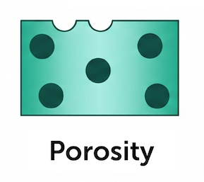
Gas porosity consists of cavities created when gas becomes trapped in molten metal or comes out of solution as the metal solidifies.
The pores are often smooth and rounded. They may appear individually, in groups, or across a larger region. Some pores open onto the casting surface, while others remain hidden until the component is machined, sectioned, scanned, or pressure tested.
Common causes of gas porosity
- Air trapped during mold filling
- Inadequate mold or die venting
- Excessive turbulence
- Moisture in molds, cores, coatings, tools, or charge material
- Dissolved hydrogen or other gases in the melt
- Poor ladle or transfer practices
- Lubricant or release-agent decomposition
- Oxide films folded into the liquid metal
How to reduce gas porosity
Improve venting so displaced air can escape rather than becoming compressed inside the cavity. Gates and runners should fill the component predictably without unnecessary splashing or abrupt changes in direction.
Depending on the alloy and casting method, melt degassing, filtration, vacuum assistance, controlled pouring, and improved moisture management may also be required.
Gas porosity should not automatically be treated as a single process problem. The American Foundry Society addresses gas porosity and shrinkage porosity separately because they have different formation mechanisms and may require different corrective actions.
2. Shrinkage Cavities and Shrinkage Porosity
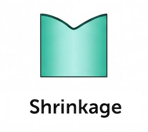
Shrinkage defects form when the casting contracts during solidification but does not receive enough additional molten metal to compensate for the lost volume.
Large, concentrated voids are generally described as shrinkage cavities. Smaller, distributed voids may be classified as micro-shrinkage or shrinkage porosity.
These defects usually form in the last regions to solidify.
Common causes of shrinkage defects
- Insufficient riser or feeder capacity
- Incorrect riser location
- Isolated thick sections
- Abrupt wall-thickness transitions
- Poor directional solidification
- Inadequate holding pressure in pressure-assisted processes
- Uncontrolled mold temperature
- Alloy solidification characteristics
A heavy boss connected to a thin wall is a typical risk. The thin wall freezes first, cutting off the supply of liquid metal to the boss. As the boss continues to solidify and contract, an internal cavity develops.
How to prevent shrinkage
The casting and feeding system should be designed so that solidification progresses toward a reservoir of molten metal. Foundries may use risers, chills, insulating sleeves, exothermic materials, local cooling, or process simulation to establish the desired solidification sequence.
Designers should core out unnecessarily heavy regions, maintain gradual section transitions, and avoid isolated masses.
Research programs focused on steel casting have identified feeding and smoother mold filling as important areas for reducing shrinkage porosity and improving casting yield.
3. Misruns
A misrun occurs when the molten metal freezes before completely filling the mold cavity.
The resulting component may have a missing edge, incomplete rib, rounded corner, partially formed hole, or another visibly unfinished feature.
Common causes of misruns
- Pouring temperature below the suitable process range
- Insufficient metal fluidity
- Thin walls
- Long or restrictive flow paths
- Slow filling
- Undersized gates
- Heat loss in the runner system
- Low mold or die temperature
- Interrupted pouring
How to prevent misruns
The manufacturer may need to adjust the pouring temperature, mold temperature, filling speed, gate area, runner length, or venting strategy.
The component itself should also be evaluated. A feature that is technically moldable under ideal conditions may still provide an unacceptably narrow production window.
Increasing wall thickness slightly, shortening the flow distance, relocating the gate, or simplifying a difficult feature may provide a more stable solution than repeatedly increasing metal temperature.
4. Cold Shuts
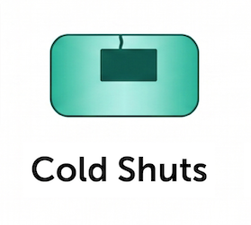
A cold shut forms when two metal streams meet but fail to fuse into one continuous body.
It often appears as a narrow line, seam, fold, or crack-like indication on the surface. Although a cold shut may look minor, it represents an interruption in the material and can reduce strength or pressure tightness.
Common causes of cold shuts
- Metal fronts cooling before they meet
- Oxide films between converging streams
- Poorly positioned gates
- Excessive flow separation
- Inconsistent filling
- Low melt or mold temperature
- Insufficient injection or pouring speed
How to prevent cold shuts
The filling system should avoid splitting the metal into streams that travel long distances before rejoining. If streams must meet, they should do so while the metal remains hot, clean, and sufficiently fluid.
Simulation can help identify low-temperature regions, delayed filling, recirculation, and difficult weld-line locations before production tooling is finalized.
5. Slag, Oxide, and Non-Metallic Inclusions

Inclusions are foreign particles trapped within the casting. Depending on the process and alloy, they may include slag, oxide films, sand, ceramic fragments, sulfides, flux residue, or refractory material.
Inclusions interrupt the metal matrix and may act as stress raisers. Their effect becomes especially important under cyclic loading, impact, pressure, or high-temperature service.
Common causes of inclusions
- Dirty charge material
- Poor skimming
- Turbulent transfer or pouring
- Oxide-film formation
- Furnace-lining erosion
- Damaged filters
- Mold or core breakdown
- Improper ladle cleaning
- Excessive holding time
How to reduce inclusions
Clean melt practices are essential. The process may include controlled skimming, ceramic filtration, proper ladle preparation, reduced drop heights, protected metal transfer, and carefully designed runner systems.
Metal should move through the system without repeatedly exposing fresh surfaces to air or folding surface oxides into the melt.
DOE casting research has reported that smoother filling can reduce splashing and air entrainment, reinforcing the importance of controlled metal flow.
6. Hot Tears and Hot Cracking
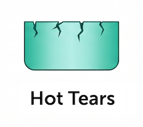
Hot tears form near the end of solidification, when the metal is weak but has begun to contract.
If the mold, core, tooling, or component geometry prevents free contraction, tensile stress develops. When the partially solidified material cannot withstand that stress, it separates.
Hot tears often have an irregular, branching appearance and commonly develop near corners, junctions, flanges, or sudden section changes.
Common causes of hot tearing
- Sharp internal corners
- Abrupt changes in wall thickness
- Restrictive cores
- Poor mold collapsibility
- Large differences in cooling rate
- Inadequate fillets
- Alloy sensitivity to hot cracking
- Long unsupported sections
How to prevent hot tears
Use generous fillets, gradual transitions, balanced wall thicknesses, and geometry that allows contraction. Mold and core systems may also need to collapse or move sufficiently during cooling.
In some situations, changing the solidification sequence, alloy specification, grain refinement practice, or cooling conditions may be necessary.
7. Warping and Dimensional Distortion
Warping occurs when different areas of a casting contract by different amounts or at different times.
Long, thin, flat, open, or asymmetrical components are particularly vulnerable. Distortion may also appear after ejection, heat treatment, machining, or removal of gates and risers as residual stresses redistribute.
Common causes of casting distortion
- Non-uniform wall thickness
- Uneven cooling
- Unbalanced component geometry
- Early removal from the mold or die
- Incorrect ejection
- Residual stress
- Inconsistent tool temperature
- Poor support during heat treatment
How to reduce warping
Design the component with balanced sections, ribs, curves, and gradual transitions. Large flat surfaces may require stiffening features.
Manufacturing controls can include balanced cooling lines, longer in-tool cooling, controlled ejection, straightening fixtures, and heat-treatment supports.
Allowance must also be made for predictable process shrinkage. However, applying a general shrinkage factor will not correct localized distortion caused by uneven thermal behavior.
8. Sand-Related Surface Defects
Sand casting can produce several defects associated with mold or core material.
These include sand inclusions, cuts, washes, scabs, erosion, penetration, rat tails, buckles, and rough surfaces.
Typical causes
- Insufficient mold strength
- Excessive metal velocity
- Poor compaction
- Incorrect binder level
- Damaged cores
- Uneven mold hardness
- Excessive pouring temperature
- Poor coating application
- Thermal expansion of the mold surface
Prevention methods
The foundry should verify sand properties, mold hardness, core strength, coating condition, gating velocity, and handling practices.
A process adjustment should address the specific mechanism. Simply increasing mold strength, for instance, may cause other problems if the mold becomes insufficiently permeable or collapsible.
9. Flash and Fins
Flash is a thin projection of metal that forms where molten metal enters a gap between mold or die surfaces.
It is especially common in pressure die casting but may occur in other processes at mold joints, core interfaces, and parting lines.
Common causes of flash
- Insufficient clamping force
- Worn or damaged tooling
- Poor die alignment
- Excessive injection pressure
- Incorrect process timing
- Foreign material on the parting surface
- Thermal expansion of the die
- Inadequate mold fastening
How to prevent flash
Inspect the tooling for wear, damage, misalignment, and contamination. Confirm that clamping force and metal pressure are appropriate for the projected casting area.
Flash can often be trimmed, but frequent or excessive flash increases finishing cost and may indicate a tooling or process condition that will continue to deteriorate.
10. Cold Shots and Flow Marks
Cold shots are small droplets or globules of metal that solidify separately and become trapped in the casting.
They form when splashing breaks the metal stream into small portions that cool before merging with the main body.
Flow marks are visible lines or patterns that indicate how metal moved across the mold or die surface. Some are cosmetic, while others are associated with incomplete fusion or poor surface formation.
Prevention methods
- Reduce splashing and free-fall distance
- Stabilize pouring
- Improve runner and gate geometry
- Maintain suitable metal and mold temperatures
- Control injection speed through each filling stage
- Prevent premature solidification in the runner system
Why Part Design Has Such a Large Effect
Process optimization cannot fully compensate for unsuitable casting geometry.
The component determines where the molten metal must travel, where air may become trapped, which regions cool first, and where thermal stress develops.
Important casting design principles include:
Keep wall thickness reasonably uniform
Uniform walls support consistent filling and cooling. Where thickness must change, use a gradual transition rather than a sudden step.
Add fillets at internal corners
Fillets improve metal flow and reduce stress concentration. Sharp internal corners can create local hot spots and restrict contraction.
Core out heavy sections
A hollow or cored feature may provide more uniform cooling than a solid mass while reducing material use and component weight.
Avoid unnecessary flow restrictions
Very thin ribs, narrow passages, sharp turns, and long flow distances increase the risk of misruns and cold shuts.
Consider gate and overflow locations early
Casting geometry should be developed with the expected filling direction, venting strategy, feeding system, and trimming requirements in mind.
NADCA’s current technical standards emphasize the combined importance of component design, tooling, processing, tolerances, alloy properties, and quality assurance in die-cast production.
How Casting Defects Are Inspected
No single inspection method can identify every defect.
The selected method depends on the material, component geometry, defect type, required sensitivity, production volume, and acceptance standard.
Visual inspection
Visual examination can reveal incomplete filling, cracks, flash, surface porosity, roughness, scabs, inclusions, and dimensional irregularities.
Good lighting, magnification, cleaning, and standardized defect samples improve consistency.
Dimensional inspection
Calipers, gauges, coordinate measuring machines, optical systems, and scanning equipment can identify shrinkage variation, warping, mismatch, and out-of-tolerance features.
Dye-penetrant inspection
Liquid penetrant testing helps reveal surface-breaking cracks and discontinuities in non-porous materials.
Magnetic-particle inspection
Magnetic-particle testing can detect surface and near-surface discontinuities in ferromagnetic cast materials.
Radiographic inspection
X-ray inspection can identify internal porosity, shrinkage cavities, inclusions, and other density variations.
NIST research into automated casting inspection has used X-ray images to locate manufacturing defects, demonstrating the importance of radiography for internal defect detection.
Ultrasonic inspection
Ultrasonic testing uses sound waves to identify internal discontinuities. Its effectiveness depends on the alloy’s grain structure, defect orientation, surface condition, and component geometry.
Computed tomography
Industrial CT creates a three-dimensional representation of internal and external features. It is useful for complex components, detailed failure analysis, and measurement of internal porosity, but it is generally more expensive than routine visual or dimensional inspection.
Pressure and leak testing
Castings used for fluid or gas containment may require pressure-decay, immersion, helium, hydrostatic, or other leak-testing methods.
A part may meet dimensional requirements while still failing a pressure-tightness specification because of connected porosity.
Destructive testing
Sectioning, microscopy, tensile testing, fatigue testing, and metallographic examination provide detailed information but permanently alter or destroy the sample.
These methods are commonly used during process development, validation, audits, and failure investigation.
A Practical Root-Cause Analysis Process
Corrective action should begin with a precise description of the defect rather than an assumption about its cause.
A practical investigation can follow these steps:
- Define the defect’s appearance, size, frequency, and location.
- Confirm when it first appeared.
- Separate affected production lots, machines, tools, cavities, shifts, and material batches.
- Determine whether the defect is internal, external, or both.
- Review process data for temperature, time, speed, pressure, vacuum, and cooling changes.
- Inspect the melt, mold, tooling, cores, filters, vents, gates, runners, and feeders.
- Compare the defect location with filling and solidification simulations.
- Change one controlled variable at a time where practical.
- Verify the result using the same inspection method that identified the problem.
- Document the confirmed root cause and update the process-control plan.
The AFS casting-defect-analysis approach similarly emphasizes a structured procedure for identifying the defect, determining its root cause, and developing corrective action rather than relying on trial and error.
Metal Casting Defect Prevention Checklist
Before releasing a component for production, review the following questions.
Component design
- Are wall thicknesses reasonably uniform?
- Have isolated heavy sections been removed or cored?
- Are thickness transitions gradual?
- Are internal corners properly filleted?
- Can the component contract without excessive restraint?
- Are long, thin, difficult-to-fill features minimized?
Filling system
- Does the metal reach all features before losing fluidity?
- Are gates positioned to support stable filling?
- Can air and process gases escape?
- Are turbulence, splashing, and oxide folding minimized?
- Are overflows and vents located near the last regions to fill?
Solidification and feeding
- Where are the final regions expected to solidify?
- Can those areas receive additional molten metal?
- Are risers, feeders, chills, or local cooling correctly positioned?
- Does the design contain avoidable hot spots?
Melt quality
- Is charge material clean, dry, and correctly identified?
- Is alloy chemistry verified?
- Are melt-treatment and degassing procedures controlled?
- Are slag and oxides removed without excessive disturbance?
- Are transfer equipment and filters maintained?
Process control
- Are metal and mold temperatures monitored?
- Are filling speed and pressure repeatable?
- Is vacuum or vent performance checked?
- Are cooling and ejection times controlled?
- Is tool wear included in preventive maintenance?
Quality control
- Are defect limits clearly defined?
- Does the inspection method detect the relevant defect?
- Are critical locations inspected with suitable sensitivity?
- Are inspection records traceable to production conditions?
- Is the response plan clear when a defect trend increases?
Frequently Asked Questions
What is the most common metal casting defect?
Porosity is among the most frequently encountered casting problems. It may be caused by trapped gas, dissolved gas, shrinkage during solidification, or a combination of mechanisms. Correctly distinguishing gas porosity from shrinkage porosity is essential because the prevention methods differ.
What is the difference between gas porosity and shrinkage porosity?
Gas porosity is associated with gas bubbles or entrapped air and often produces smoother, rounded cavities. Shrinkage porosity develops when solidifying metal contracts without adequate liquid-metal feeding and often has a more irregular or interconnected shape.
Can casting defects be completely eliminated?
A well-controlled process can reduce defects substantially, but expecting every casting process to produce mathematically perfect material is usually unrealistic. The engineering objective is to keep relevant discontinuities below clearly defined acceptance limits while maintaining consistent production.
Which casting defects are the most dangerous?
Cracks, connected porosity, large shrinkage cavities, inclusions, and severe cold shuts can be especially serious because they interrupt the load-bearing material. Their importance depends on size, orientation, location, applied stress, operating temperature, and service environment.
Can machining remove casting defects?
Machining can remove superficial defects or expose sound material beneath the surface. However, it cannot repair internal porosity, deep inclusions, hot tears, or structural discontinuities. Machining may also reveal defects that were previously hidden.
How does simulation help prevent casting defects?
Flow and solidification simulation can predict filling patterns, air entrapment, temperature distribution, hot spots, solidification sequence, and potential shrinkage regions. Simulation does not replace production validation, but it can reduce tooling revisions and accelerate process development.
How are internal casting defects detected?
Common methods include radiography, industrial CT, ultrasonic testing, leak testing, and destructive sectioning. The best method depends on the alloy, component geometry, expected defect type, and required detection limit.
What information should be included on a casting drawing?
The drawing and purchasing specification should identify the alloy, heat treatment, critical dimensions, machining allowance, surface-finish requirements, pressure-tightness requirements, inspection standard, defect acceptance criteria, and any critical component zones.
Conclusion
Metal casting defects are usually the visible result of an underlying interaction between molten-metal quality, component design, mold filling, feeding, solidification, tooling, and process stability.
Effective prevention begins before metal is poured. Uniform wall thickness, gradual transitions, appropriate fillets, controlled flow paths, adequate venting, and properly fed solidification regions reduce the number of opportunities for defects to form.
When a defect does occur, the most reliable response is a structured investigation supported by inspection data and process records. Changing multiple parameters without confirming the failure mechanism may temporarily hide the problem while making the process less predictable.
By combining design-for-casting principles, clean melt handling, controlled filling, directional solidification, simulation, preventive maintenance, and appropriate inspection, manufacturers can reduce scrap, improve repeatability, and deliver cast components with more dependable performance.