CNC machining can produce extremely precise components, but dimensional accuracy does not always end when the cutting tool stops.
A part may leave the machine within tolerance and then gradually bend, twist, bow, or change size after unclamping, cooling, heat treatment, anodizing, or simply sitting for several hours.
This phenomenon is known as machining distortion or deformation.
In most cases, CNC parts deform after machining because internal stresses inside the material become unbalanced when material is removed. Heat generated during machining, aggressive cutting parameters, poor workholding, thin-wall geometry, and material condition can make the problem significantly worse.
Understanding why this happens is essential when manufacturing precision components, particularly large plates, thin walls, aerospace parts, housings, rings, and components requiring tight flatness or positional tolerances.
What Causes CNC Parts to Deform After Machining?
The most common causes are:
- residual stress inside the raw material;
- excessive heat generated during machining;
- removal of too much material from one side;
- aggressive clamping forces;
- thin or unsupported geometry;
- unsuitable machining strategy;
- material instability;
- heat treatment before or after machining;
- insufficient rough-machining allowance;
- temperature differences during inspection.
Often, several of these factors act together.
For example, a thin aluminium plate may already contain residual stress from rolling. Machining most of the material from one face releases that stress unevenly. Strong clamps can temporarily force the plate flat during machining, but after the clamps are removed, the component bows.
The machine did not necessarily produce the wrong geometry. The geometry changed after the forces holding the part were released.
1. Residual Stress in the Raw Material
Residual stress is one of the most important causes of CNC machining distortion.
Metal manufacturing processes such as:
- rolling;
- forging;
- extrusion;
- casting;
- welding;
- heat treatment;
- straightening;
can leave internal stresses locked inside the material.
These stresses may exist even when the material appears perfectly flat and stable.
When CNC machining removes material, the balance of those stresses changes.
Imagine a plate where internal forces are balanced throughout its thickness.
If 5 mm is removed from one side but only 1 mm from the opposite side, the stress distribution becomes asymmetrical. The remaining material may move to establish a new equilibrium.
The result can be:
- bowing;
- twisting;
- bending;
- ovality;
- loss of flatness;
- dimensional changes.
The effect becomes more noticeable as more material is removed.
Why Does Material Move After It Is Unclamped?
Machine fixtures can temporarily hide deformation.
Suppose a slightly bowed aluminium plate is clamped against a flat fixture.
The clamps force the component flat.
The CNC machine then produces the required dimensions while the part is restrained.
Once the clamps are released, however, the original forces return.
The plate may spring upward.
This is sometimes called springback.
For this reason, a measurement taken while a component is heavily clamped may not represent the geometry of the finished free-state component.
2. Uneven Material Removal
Removing large amounts of material from only one side of a component is particularly likely to cause distortion.
Consider a 30 mm aluminium plate that must be machined to 20 mm.
If almost all 10 mm is removed from one face, any residual stress present through the thickness becomes unbalanced.
A better strategy may be to alternate between surfaces.
For example:
- remove material from side A;
- flip the component;
- remove material from side B;
- allow the component to relax;
- finish side A;
- finish side B.
This does not eliminate residual stress, but it can release it more symmetrically.
For precision components, machining strategy can therefore be just as important as machine accuracy.
3. Heat Generated During CNC Machining
Machining generates heat through friction and plastic deformation.
Heat enters:
- the cutting tool;
- the chips;
- the workpiece;
- the machine structure.
If the component becomes significantly warmer during machining, thermal expansion can temporarily change its dimensions.
When the component later cools to room temperature, it contracts.
For most ordinary tolerances this change may be insignificant.
For precision machining, however, even small temperature differences matter.
The approximate dimensional change can be expressed as:
ΔL = α × L × ΔT
where:
- ΔL = dimensional change;
- α = coefficient of thermal expansion;
- L = component length;
- ΔT = temperature change.
Aluminium is particularly sensitive because its thermal expansion is relatively high.
A long aluminium component measured while warm can therefore produce a noticeably different measurement once it reaches the controlled temperature of an inspection room.
Example: Temperature Effect on an Aluminium Part
Consider an aluminium component approximately 500 mm long.
If its temperature changes by 10°C, the dimensional change can be around:
0.115 mm
depending on the exact aluminium alloy.
That is much larger than a ±0.02 mm machining tolerance.
This does not mean aluminium cannot be machined precisely.
It means temperature must be controlled when extremely tight tolerances are required.
4. Thin Walls and Thin Floors
Thin sections are among the most difficult features to machine accurately.
A thick block of material has substantial stiffness.
A 1-2 mm wall does not.
Thin features can deform because of:
- cutting pressure;
- clamping pressure;
- residual stress;
- vibration;
- thermal expansion;
- insufficient support.
The tool itself can push a thin wall away during cutting.
After the tool passes, the wall springs back.
This may create:
- incorrect wall thickness;
- taper;
- waviness;
- poor flatness;
- dimensional variation.
Very deep pockets with thin floors can behave similarly.
Why Thin-Wall CNC Parts Are Difficult
Imagine machining a pocket inside an aluminium housing.
At the beginning, the billet is rigid.
As material is removed, the walls become thinner and the component becomes less stiff.
The same cutting force that produced almost no movement during roughing may produce measurable movement during finishing.
This is why finishing strategies for thin-wall components often require:
- lighter cuts;
- reduced radial engagement;
- sharp cutting tools;
- good support;
- balanced material removal;
- multiple finishing passes.
5. Excessive Clamping Force
More clamping force does not always mean better machining.
Clamping must prevent movement during cutting, but excessive force can distort the workpiece.
The problem is especially common with:
- thin plates;
- rings;
- tubes;
- thin-wall housings;
- plastic components;
- large aluminium parts.
For example, a thin ring may become slightly oval when compressed by a three-jaw chuck.
The bore is then machined perfectly round while the ring is clamped.
After the jaws release, the outside diameter returns toward its original geometry—and the newly machined bore may become slightly oval.
This is why workholding strategy becomes critical for precision turning.
6. Material Type and Condition
Different materials behave differently during machining.
Some materials are naturally more dimensionally stable than others.
Material condition can also be as important as the alloy itself.
For aluminium, conditions such as:
- T6;
- T651;
- T6511;
can influence dimensional stability.
Stress-relieved plate is often preferred for heavily machined precision components because reducing residual stress decreases the tendency to distort when large amounts of material are removed.
However, no material condition makes deformation completely impossible.
Part geometry and machining strategy still matter.
7. Rolled Plate Can Behave Differently From Cast Tooling Plate
Two aluminium plates with similar mechanical properties may behave very differently during machining.
Rolled aluminium plate can contain residual stresses created during manufacturing and straightening.
Precision cast tooling plate is produced specifically to provide improved dimensional stability and flatness.
For components involving:
- large pockets;
- extensive material removal;
- large flat surfaces;
- tight flatness requirements;
material selection should therefore consider not only strength and price, but also dimensional stability after machining.
8. Forged Components Can Also Move
Forging improves mechanical properties, but the forging process can introduce complex internal stress patterns.
If a forged blank requires significant machining, removing the outer material may alter this stress balance.
Large forged rings and shafts are particularly sensitive because large volumes of material may be removed before final dimensions are achieved.
A typical manufacturing sequence may therefore involve:
rough machining → stress relieving → semi-finishing → final machining
rather than machining directly from the forging to final dimensions in a single operation.
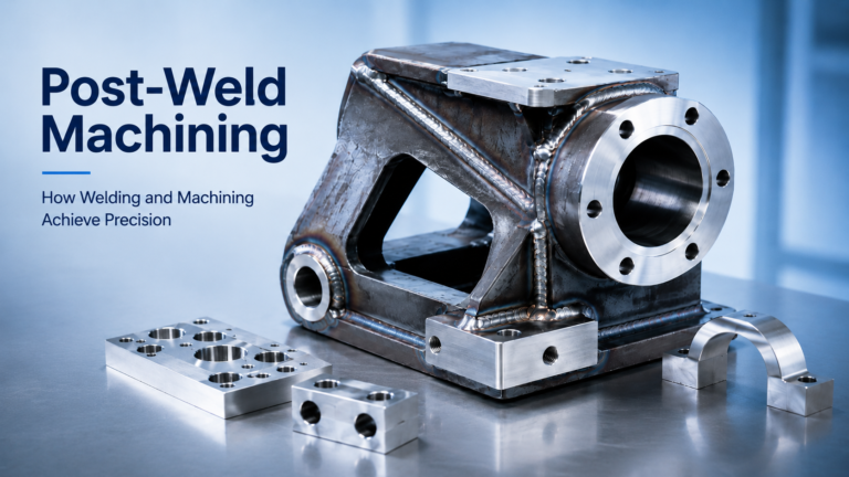
9. Welding Before CNC Machining
Welded assemblies contain some of the highest residual stresses encountered in manufacturing.
During welding, a small region of material becomes extremely hot while nearby material remains much cooler.
As the weld cools, contraction produces residual stress and distortion.
Machining a welded frame or housing can release part of those stresses.
Large welded structures may therefore change shape after machining.
For precision welded components, manufacturers may use:
- controlled welding sequences;
- symmetrical weld placement;
- stress-relief heat treatment;
- vibration stress relief in certain applications;
- rough machining before final finishing.
10. Rough Machining Directly to Final Size
Removing large amounts of material and immediately finishing the component can create problems.
A more stable process is often:
Rough machining → relaxation → semi-finishing → finishing
During rough machining, most of the material is removed.
The component is then allowed to release internal stress.
If movement occurs, sufficient material remains for the finishing operation to restore the required geometry.
The amount of finishing allowance depends on:
- component size;
- material;
- geometry;
- tolerance;
- heat treatment;
- amount of material removed.
There is no universal allowance suitable for every CNC part.
11. Machining Sequence Matters
The order in which features are machined can strongly influence the final geometry.
Consider a component containing:
- one large pocket;
- several precision bores;
- tight positional tolerances.
If the bores are finished first and the large pocket is machined afterward, removing the pocket material may distort the component and shift the finished bores.
A better strategy may be:
- rough machine the outside geometry;
- rough machine large pockets;
- allow stress redistribution;
- semi-finish critical surfaces;
- finish datum surfaces;
- finish precision bores and holes last.
Critical features are generally finished after operations most likely to cause distortion.
12. Part Geometry Has a Major Influence
Some geometries are naturally more susceptible to deformation.
Typical examples include:
Large plates
Large, thin plates can bow after facing or pocket machining.
Rings
Thin rings may become oval because of chuck pressure or residual stress.
Long shafts
Long, slender shafts can bend because of cutting forces and internal stresses.
Thin housings
Large pockets can remove most of the original material, drastically reducing structural stiffness.
Asymmetrical parts
Removing significantly more material from one region than another increases the risk of uneven stress release.
A CNC machine can be extremely accurate while still producing an unstable component if the part geometry itself makes deformation difficult to control.
13. Heat Treatment Can Change Dimensions
Processes such as:
- hardening;
- carburizing;
- nitriding;
- annealing;
- stress relieving;
can alter component dimensions.
Hardening is particularly important because transformation within the metal structure can produce both dimensional change and distortion.
When extremely precise dimensions are required after heat treatment, manufacturers may intentionally leave additional machining or grinding allowance.
A typical process could be:
rough machining → heat treatment → grinding / hard turning → final inspection
The correct sequence depends on the material, hardness and tolerance requirements.
14. Surface Treatments Can Also Affect Precision
Some finishing processes add material to the surface.
Examples include:
- hard anodizing;
- electroless nickel plating;
- zinc plating;
- chrome plating.
If a bore has a tight tolerance, coating thickness must be considered before machining the pre-coating dimension.
Other processes may create thermal or mechanical effects.
Therefore, the engineering drawing should clearly define whether a tolerance applies:
before surface treatment or after surface treatment.
For precision mating surfaces, this distinction can be critical.
15. Plastic CNC Parts Have Their Own Deformation Problems
Metals are not the only materials that move after machining.
Engineering plastics such as:
- POM;
- PEEK;
- PA;
- PTFE;
- UHMW-PE;
can also deform considerably.
Plastics may contain stresses from extrusion or molding and generally have lower stiffness than metals.
Many engineering plastics are also considerably more sensitive to temperature.
During machining, excessive heat may cause:
- local expansion;
- softening;
- dimensional instability;
- poor surface finish.
Some plastics may continue changing dimensions after machining as temperature or moisture conditions change.
How Can CNC Machining Deformation Be Reduced?
There is rarely one single solution.
Successful distortion control normally combines material selection, machining strategy, workholding and inspection.
1. Use Stress-Relieved Material
Where dimensional stability is critical, select raw material specifically suited for precision machining.
This is particularly important for components where a large percentage of the original billet will be removed.
2. Rough Machine Before Finishing
Remove most of the material during a separate roughing operation.
Leave sufficient stock for final machining.
This allows much of the stress redistribution to occur before critical surfaces are finished.
3. Machine Both Sides Progressively
For plate-like components, avoid removing all the material from one side where possible.
Alternate machining between surfaces to maintain a more balanced stress distribution.
4. Reduce Clamping Forces
Use enough force to hold the component securely—but no more than necessary.
Consider:
- soft jaws;
- vacuum fixtures;
- distributed clamping;
- custom fixtures;
- low-distortion jaw designs.
The optimal fixture supports the component without forcing it into an artificial shape.
5. Reduce Cutting Forces During Finishing
Finishing passes should generally create less cutting force than roughing operations.
Possible measures include:
- smaller depth of cut;
- reduced radial engagement;
- sharp tools;
- optimized feeds;
- appropriate tool geometry.
This is particularly important for thin walls and slender features.
6. Control Machining Temperature
Good coolant application and appropriate cutting parameters help limit excessive workpiece heating.
For extremely precise parts, the component should also be allowed to stabilize before final inspection.
7. Finish Critical Features Late
Precision bores, datum surfaces and tightly controlled geometry should preferably be finished after major material-removal operations.
Otherwise subsequent machining may alter their position.
8. Consider Stress Relief Between Operations
For difficult components, thermal stress relief may be justified between rough machining and finishing.
This adds cost and lead time, but it can significantly improve stability for demanding parts.
CNC Deformation vs CNC Machine Accuracy
This distinction is important.
If a machined component bends after unclamping, that does not automatically mean the CNC machine is inaccurate.
Three different factors must be considered:
Machine accuracy
How accurately the CNC machine positions and moves.
Process accuracy
How well tooling, workholding, cutting parameters and machining strategy produce the required feature.
Part stability
Whether the material maintains that geometry after machining.
A CNC machine capable of positioning within a few micrometres cannot prevent an unstable workpiece from moving after machining.
Why Can a Part Measure Correctly on the Machine but Fail Inspection Later?
One common scenario is:
- the component is tightly clamped;
- machining is completed;
- dimensions are checked while the component remains constrained;
- the component is removed;
- internal stress causes movement;
- inspection later detects flatness or dimensional errors.
Temperature can produce a similar effect.
A component measured directly after machining may still be warm.
After cooling, its dimensions change slightly.
For precision work, measurement conditions must therefore be controlled.
How Much CNC Part Deformation Is Acceptable?
There is no universal acceptable amount.
It depends entirely on the drawing and function of the component.
A 0.10 mm distortion may be irrelevant for a large fabricated bracket but completely unacceptable for:
- a precision bearing housing;
- a sealing surface;
- an optical component;
- a locating fixture;
- a precision machine assembly.
Designers should therefore apply tight flatness, parallelism, position and dimensional tolerances only where they are functionally necessary.
Unnecessarily tight tolerances can make distortion control substantially more expensive.
How Does Part Deformation Affect CNC Machining Cost?
Controlling deformation often requires additional operations.
These may include:
- purchasing stress-relieved material;
- rough machining;
- intermediate inspection;
- additional setups;
- stress-relief treatment;
- component relaxation time;
- custom fixtures;
- semi-finishing;
- grinding;
- final CMM inspection.
Consequently, a component requiring ±0.01 mm dimensional accuracy and extremely tight flatness can cost considerably more than an otherwise identical part with general machining tolerances.
The drawing should therefore distinguish between functionally critical tolerances and dimensions that do not require exceptional precision.
Example: Large Aluminium Plate With Tight Flatness
Consider a plate machined from aluminium billet.
Raw material: 30 mm thick
Finished thickness: 15 mm
Component size: 600 × 400 mm
Flatness requirement: 0.05 mm
Machining 15 mm entirely from one face can create significant distortion.
A more stable process may involve:
- rough facing side A;
- flipping the component;
- rough facing side B;
- rough machining pockets;
- allowing the component to stabilize;
- semi-finishing both sides;
- finishing the reference surface;
- finishing the opposite surface;
- checking flatness in a controlled condition.
Although this involves additional handling, it can significantly improve dimensional stability.
Design Tips for Minimizing CNC Part Distortion
Designers can reduce manufacturing risk before the part reaches the machine.
Where possible:
- avoid extremely thin walls;
- maintain reasonably uniform wall thickness;
- avoid unnecessarily deep pockets;
- avoid removing most of the billet from only one side;
- use ribs to increase stiffness;
- define realistic flatness tolerances;
- specify appropriate material conditions;
- indicate whether dimensions apply before or after coating;
- identify genuinely critical dimensions on the drawing.
A manufacturable design is not simply one that can be cut by a CNC machine.
It should also remain stable after machining.
Frequently Asked Questions
Why does aluminium warp after CNC machining?
Aluminium can warp because residual stresses inside rolled, forged or extruded material are released when material is removed. Thin geometry, uneven machining, heat and excessive clamping can increase the effect.
Can CNC machining relieve internal stress?
Machining does not normally remove all internal stress. Instead, removing material changes how existing stresses are balanced, which can cause the component to move.
Why does my CNC part bend after removing it from the fixture?
The fixture may be forcing the component into a different shape. When clamping pressure is removed, the part returns toward its natural stress equilibrium.
Can stress-relieved aluminium still deform?
Yes. Stress-relieved material greatly reduces the risk, but geometry, machining strategy, temperature and workholding can still produce distortion.
Should CNC parts rest between roughing and finishing?
For some precision or heavily machined components, allowing the part to stabilize between operations can be beneficial. More demanding applications may require formal stress-relief treatment.
Does CNC machining generate enough heat to change dimensions?
Yes. Thermal expansion can become significant when tight tolerances or large component dimensions are involved.
Why do thin-wall CNC parts distort?
Thin walls have low stiffness and can deflect under cutting and clamping forces. Removing surrounding material can also release residual stresses that were previously balanced.
Can machining sequence reduce deformation?
Yes. Balanced material removal, roughing before finishing, alternating surfaces and machining precision features toward the end of the process can significantly improve stability.
Conclusion
CNC part deformation is rarely caused by one factor alone.
It is usually the result of an interaction between material stress, geometry, heat, cutting forces, clamping and machining sequence.
The most effective way to minimize distortion is to consider dimensional stability from the beginning of the manufacturing process.
Selecting appropriate material, balancing material removal, separating roughing from finishing, minimizing clamping forces, controlling temperature and finishing critical features last can dramatically improve final accuracy.
For highly precise CNC components, the question should therefore not only be:
Can the machine produce this tolerance?
A better question is:
Can the component maintain this tolerance after machining, unclamping, cooling and finishing?
That distinction is one of the most important considerations in precision CNC manufacturing.