Precision parts manufacturing demands exacting control at every stage to meet tight tolerances whilst managing costs effectively. Manufacturers face persistent challenges balancing dimensional accuracy with production efficiency, particularly when working with complex geometries and advanced materials. This comprehensive guide explores the complete precision parts manufacturing process from design review through final inspection, revealing how advanced CNC techniques, digital twins, and integrated surface treatments transform workflow optimisation. Western European manufacturing professionals will discover actionable strategies to enhance quality, reduce defects, and achieve consistent results in high-stakes production environments.
Table of Contents
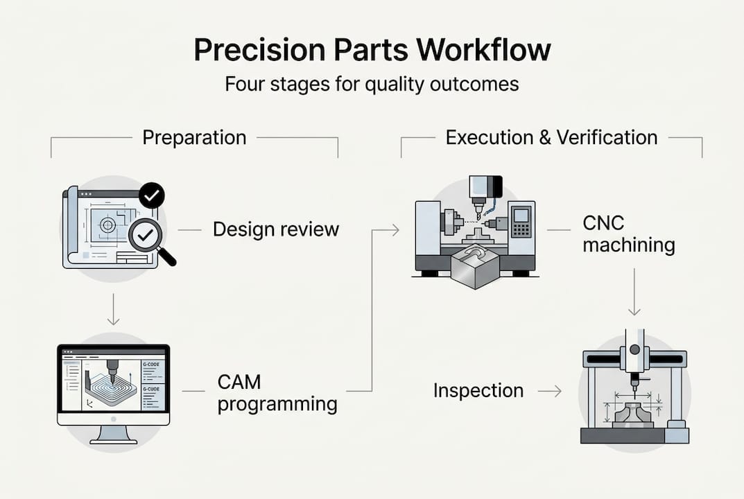
- Preparation Stage: Design Review And Materials Planning
- Execution Stage Part 1: CNC Machining And Process Control
- Execution Stage Part 2: Tool Wear Management And Deformation Control
- Verification Stage: Inspection And Surface Treatment Integration
- Why Choose MegaMETA For Precision Parts Manufacturing
- Frequently Asked Questions
Key takeaways
| Point | Details |
|---|---|
| Workflow stages | Design review, CAM programming, multi-stage CNC machining, inspection, and surface treatment form the complete precision manufacturing sequence |
| Advanced CNC control | 5-axis machining and real-time tool wear monitoring deliver tolerances to ±5μm whilst minimising setups and maintaining surface integrity |
| Digital twin technology | Predictive simulation prevents thin-walled part deformation and enables proactive compensation strategies during machining operations |
| Cost-tolerance balance | Optimising tolerance specifications prevents over-engineering expenses whilst ensuring parts meet functional requirements without quality compromise |
| Integrated inspection | In-process CMM and probing systems enable real-time error correction, reducing scrap rates and ensuring dimensional accuracy throughout production |
Preparation stage: design review and materials planning
Successful precision manufacturing begins well before the first cutting tool touches raw material. The Precision parts manufacturing workflow typically begins with CAD design review and DFM analysis, followed by CAM programming, establishing the foundation for everything that follows. Design engineers scrutinise CAD models to identify potential manufacturability issues, examining dimensional tolerances, geometric complexities, and surface finish requirements against available CNC capabilities. This early intervention prevents costly mid-production discoveries that derail schedules and budgets.
Design for manufacturability analysis transforms theoretical designs into practical production plans. Engineers evaluate whether specified tolerances genuinely serve functional needs or represent unnecessary precision that inflates costs. They assess tooling accessibility for internal features, identify opportunities to consolidate setups through strategic feature placement, and flag geometries requiring specialised fixturing. Material selection follows this analysis, balancing mechanical properties like tensile strength and hardness against machinability ratings and procurement costs. Aluminium alloys offer excellent machinability for aerospace components, whilst hardened steels demand carbide tooling and slower cutting speeds for automotive applications.
CAM programming translates validated designs into executable machine instructions. Programmers generate optimised toolpaths that minimise air cutting time, reduce tool changes, and maintain consistent chip loads throughout operations. They simulate entire machining sequences virtually, detecting potential collisions between cutting tools, fixtures, and workpieces before committing to production. Material traceability documentation accompanies raw stock from certified suppliers, providing mill test reports that verify chemical composition and mechanical properties meet specification requirements.
Pro Tip: Establish material verification protocols that cross-reference supplier certifications with independent testing for critical aerospace or medical components, ensuring complete traceability chains satisfy regulatory audits.
Critical preparation elements include:
- Tolerance stack-up analysis ensuring cumulative dimensional variations remain within acceptable limits across assembly interfaces
- Fixture design planning that maintains part rigidity during aggressive cutting operations without inducing stress concentrations
- Tool selection matching insert geometries and coating technologies to specific workpiece materials and cutting conditions
- Setup reduction strategies grouping similar operations to minimise repositioning errors and improve throughput efficiency
Execution stage part 1: CNC machining and process control
Precision CNC machining unfolds through carefully orchestrated stages, each serving distinct purposes in transforming raw material into finished components. Multi-stage CNC machining stages include roughing, semi-finishing, and finishing with milling, turning, drilling, and boring, progressively refining dimensions and surface characteristics. Roughing operations remove bulk material rapidly using aggressive depth of cut and feed rate parameters, prioritising material removal rates over surface quality. Semi-finishing passes reduce remaining stock allowances whilst improving dimensional accuracy, preparing surfaces for final precision cuts.
Finishing operations deliver specified tolerances and surface finishes through light cuts with sharp tooling and optimised parameters. Milling creates complex contoured surfaces and pockets, turning generates cylindrical features and threaded sections, drilling produces initial hole geometries, and boring achieves precise diameter tolerances for bearing fits and alignment pins. 5-axis simultaneous machining enables tight tolerances ±5μm and minimises setups, maintaining consistent datum references throughout complete machining sequences. This capability proves invaluable for aerospace turbine blades and medical implants where geometric complexity demands continuous tool axis orientation.
Thermal management prevents dimensional errors caused by heat-induced expansion in both workpieces and machine structures. Constant engagement toolpaths distribute cutting forces evenly, avoiding sudden temperature spikes that distort thin-walled sections. Flood coolant systems remove heat from cutting zones whilst flushing chips away from precision surfaces. Temperature-controlled manufacturing environments maintain ±1°C stability, preventing thermal drift in machine tool components that would compromise positional accuracy over extended production runs.
| Machining stage | Primary purpose | Typical parameters | Surface finish achieved |
|---|---|---|---|
| Roughing | Bulk material removal | High feed rates, deep cuts, rapid spindle speeds | Ra 3.2-6.3 μm |
| Semi-finishing | Dimensional refinement | Moderate feeds, reduced depth of cut | Ra 1.6-3.2 μm |
| Finishing | Final tolerance and surface quality | Light cuts, high spindle speeds, sharp tools | Ra 0.4-1.6 μm |
| Super-finishing | Ultra-precision applications | Minimal depth of cut, optimised tool geometry | Ra <0.4 μm |
Process control systems monitor critical parameters continuously throughout machining cycles. Adaptive feed rate controls adjust cutting speeds based on real-time spindle load measurements, preventing tool breakage when encountering hard spots or material inconsistencies. Vibration sensors detect chatter onset before surface finish degradation occurs, triggering automatic parameter adjustments that restore stable cutting conditions. Spindle thermal compensation algorithms apply position offsets that counteract predictable thermal growth patterns in machine structures.
Pro Tip: Implement statistical process control charting for critical dimensions, plotting measurement data from consecutive parts to identify gradual process drift before tolerances are exceeded, enabling proactive tool changes rather than reactive scrap generation.
Essential CNC machining services control elements:
- Spindle speed optimisation matching surface footage requirements to tool diameter and material properties
- Feed rate calibration balancing productivity targets against tool life expectations and surface finish specifications
- Depth of cut selection considering material hardness, tool rigidity, and available machine power
- Coolant delivery strategies directing high-pressure fluid streams precisely at cutting edges for maximum heat removal
- Tool engagement monitoring ensuring consistent chip loads throughout complex toolpath geometries
Execution stage part 2: tool wear management and deformation control
Tool condition directly determines whether precision parts meet dimensional and surface finish specifications. Tool wear monitoring is critical, as flank wear >0.2mm doubles surface roughness (Ra), transforming acceptable components into expensive scrap. Advanced manufacturers deploy AI-powered monitoring systems that analyse acoustic emissions, cutting force signatures, and vibration patterns to detect progressive wear before quality degradation occurs. Machine learning algorithms trained on historical tool life data predict remaining useful life, scheduling replacements during planned production gaps rather than mid-batch failures.
Multi-step hole making sequences achieve superior accuracy for critical features like bearing bores and hydraulic passages. Spot drilling centres holes precisely, preventing drill bit wander on curved or angled surfaces. Drilling removes bulk material efficiently, followed by reaming that improves diameter accuracy and surface finish. Boring operations deliver final diameter tolerances within ±10μm whilst maintaining excellent cylindricity and surface texture. This methodical approach outperforms single-operation drilling for demanding applications where concentricity and positional accuracy prove critical.
Digital twins simulate thin-walled part deformation to prevent defects and rework, revolutionising how manufacturers approach delicate components. Virtual models incorporate material properties, fixture constraints, and cutting force predictions to simulate how parts will deform during machining. Engineers use these insights to design adaptive toolpaths that compensate for predicted deflections, applying strategic stock allowances where material removal will cause distortion. Real-time sensor feedback validates simulation accuracy, enabling continuous model refinement that improves prediction reliability across production batches.
“Tool wear progression from initial contact through catastrophic failure follows predictable patterns, yet many manufacturers still rely on fixed replacement intervals that waste tool life or risk quality failures. Condition-based monitoring transforms tool management from guesswork into data-driven precision, reducing tooling costs by 20-30% whilst improving part consistency.”
Vibration control becomes paramount in micro-milling operations where tool diameters measure mere millimetres and cutting depths span micrometres. Chatter resonance amplifies rapidly in slender tools, creating surface waviness that violates tolerance specifications. Optimised stepover ratios distribute cutting forces favourably, whilst variable helix angle tools disrupt harmonic frequencies that trigger vibration. High-speed spindles operating at 40,000+ RPM enable reduced chip loads that minimise deflection forces on delicate tooling.
Pro Tip: Monitor tool flank wear thresholds religiously, establishing replacement criteria at 0.15mm VB for finishing operations to maintain surface roughness specifications, preventing the exponential quality degradation that occurs beyond this critical threshold.
Advanced deformation control strategies:
- Symmetrical roughing sequences removing material from opposing sides alternately to balance residual stresses
- Stress-relief heat treatments between roughing and finishing operations for components machined from pre-stressed forgings
- Fixture design incorporating strategic support points that constrain deflection without inducing localised stress concentrations
- Climb milling orientation directing cutting forces into rigid fixture elements rather than cantilevered part sections
Verification stage: inspection and surface treatment integration
Quality verification integrates seamlessly throughout precision manufacturing workflows rather than occurring solely at completion. In-process inspection uses coordinate measuring machines (CMM) or probing to ensure dimensional accuracy, enabling immediate corrective action when measurements reveal dimensional drift. On-machine probing systems measure critical features without removing parts from fixtures, maintaining datum consistency whilst eliminating handling errors. Automated inspection cycles execute between roughing and finishing operations, confirming adequate stock remains for final passes and validating that previous operations achieved positional accuracy.
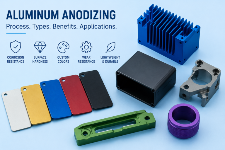
Post-machining surface treatments like anodizing, passivation, and grinding achieve required surface finish and corrosion resistance, transforming functional components into application-ready parts. Anodizing aluminium components creates protective oxide layers that resist corrosion in marine and aerospace environments whilst offering decorative colour options. Passivation removes free iron contamination from stainless steel surfaces, maximising corrosion resistance for medical instruments and food processing equipment. Precision grinding delivers mirror finishes below Ra 0.2μm for hydraulic valve components and optical mounting surfaces.
| Inspection method | Measurement capability | Typical accuracy | Application context |
|---|---|---|---|
| CMM touch probe | 3D dimensional verification | ±2-5 μm | Complex geometries, multiple features |
| Laser scanning | Surface profile capture | ±10-20 μm | Reverse engineering, contour validation |
| Optical comparator | 2D profile inspection | ±5 μm | Simple geometries, edge quality |
| Surface roughness tester | Texture quantification | Ra 0.01 μm resolution | Finish verification, process control |
| Surface treatment | Primary benefit | Typical applications | Post-treatment considerations |
|---|---|---|---|
| Anodizing | Corrosion protection, wear resistance | Aerospace, marine components | Dimensional growth 10-25 μm per surface |
| Passivation | Corrosion resistance enhancement | Medical, food processing parts | No dimensional change |
| Precision grinding | Ultra-fine surface finish | Hydraulic components, bearing surfaces | Removes 50-200 μm material |
| Shot peening | Fatigue life improvement | High-stress components | Surface compression, slight texture |
Standardised quality assurance in precision manufacturing workflows ensure repeatability across production batches and manufacturing facilities. Documented inspection plans specify measurement frequencies, acceptance criteria, and corrective action protocols that guide quality technicians through verification sequences. Statistical sampling strategies balance inspection thoroughness against production efficiency, applying 100% inspection to critical safety features whilst using representative sampling for non-critical dimensions.
Comprehensive verification workflow steps:
- First article inspection validating setup accuracy before committing to batch production
- In-process dimensional checks at strategic operation intervals confirming process stability
- Surface finish measurements ensuring grinding or polishing operations achieve specified Ra values
- Final CMM inspection documenting complete dimensional compliance for traceability records
- Surface treatment services verification confirming coating thickness, adhesion, and appearance meet specifications
- Material certification review cross-referencing finished part documentation with original raw material traceability
Integrating inspection data with manufacturing execution systems creates closed-loop quality control. Measurement results automatically update process control charts, triggering alerts when statistical trends indicate impending tolerance violations. This proactive approach prevents defect generation rather than merely detecting problems after occurrence, reducing scrap rates whilst improving overall equipment effectiveness.
Why choose MegaMETA for precision parts manufacturing
Mastering precision parts manufacturing workflows requires more than theoretical knowledge; it demands practical expertise backed by advanced capabilities and proven quality systems. MegaMETA delivers precision CNC machining services utilising multi-axis equipment and sophisticated process controls that consistently achieve demanding tolerances. Our integrated approach combines machining excellence with comprehensive surface treatment capabilities, ensuring parts meet both dimensional specifications and functional surface requirements without coordinating multiple suppliers.

Certified ISO 9001 quality assurance systems provide the documented processes and traceability frameworks that regulated industries demand. We collaborate closely with engineering teams to optimise manufacturing workflows, balancing precision requirements against cost realities through intelligent process design. Whether you need aerospace components with ±5μm tolerances or high-volume production parts requiring consistent quality, our technical expertise and manufacturing infrastructure deliver reliable results that support your competitive success.
Frequently asked questions
What is the typical workflow for precision parts manufacturing?
Precision manufacturing follows a structured sequence beginning with CAD design review and design for manufacturability analysis to identify potential issues before production. CAM programming creates optimised toolpaths, followed by multi-stage CNC machining progressing from roughing through finishing operations. In-process inspection validates dimensions at critical intervals, enabling immediate corrections when drift occurs. Final surface treatments like anodizing or precision grinding prepare parts for application-specific requirements, with comprehensive documentation ensuring complete traceability throughout the workflow.
How does tool wear affect manufacturing precision?
Tool wear beyond flank wear VB 0.2mm doubles surface roughness (Ra), creating unacceptable surface finishes that violate specifications and generate scrap. Progressive wear also degrades dimensional accuracy as cutting edge geometry changes, introducing size variations and positional errors. Advanced monitoring systems detect wear progression through acoustic emissions and vibration analysis, enabling proactive tool replacement before quality degradation occurs. Condition-based tool management reduces costs by maximising useful tool life whilst maintaining consistent part quality across production batches.
What technologies help control part deformation during machining?
Digital twins simulate thin-walled part deformation to prevent defects and rework, predicting how cutting forces and thermal effects will distort delicate geometries during material removal. These virtual models enable engineers to design compensated toolpaths that account for predicted deflections, maintaining dimensional accuracy despite machining-induced distortion. Five-axis CNC machining reduces setup count and distributes cutting forces more evenly across part surfaces, minimising cumulative stress that causes warping. Real-time sensor monitoring adjusts feed rates and depth of cut dynamically when vibration or excessive deflection is detected, preventing chatter that degrades surface finish and dimensional control.
Why is balancing tolerance and cost important in workflow optimisation?
Specifying tighter tolerances than functionally necessary drives exponential cost increases through extended machining time, increased tool consumption, and higher scrap rates. Over-tolerancing inflates expenses without improving performance, wasting resources on precision that provides no application benefit. Optimised tolerance specifications ensure parts meet functional requirements reliably whilst minimising manufacturing complexity and cost. Collaborative design reviews between engineering and manufacturing teams identify opportunities to relax non-critical tolerances, concentrating precision where it genuinely matters for assembly fits, sealing surfaces, and functional interfaces. This strategic approach delivers cost-effective production without compromising quality or performance in actual service conditions.