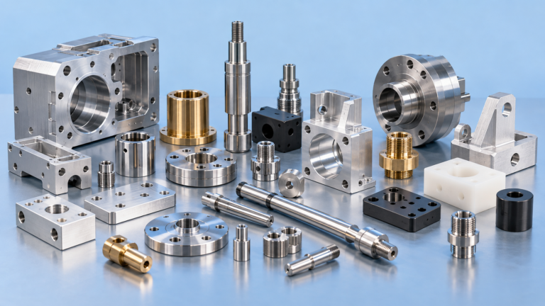
Helical milling is a CNC machining method in which a rotating cutting tool follows a circular path while simultaneously moving along the Z-axis. This creates a spiral, or helical, toolpath that can produce holes, bores, circular pockets and other internal features larger than the diameter of the cutter itself.
For manufacturers, engineers and purchasing teams, the main advantage is flexibility. Instead of keeping a separate drill for every hole diameter, one suitable end mill can machine several diameters simply by changing the CNC program.
Helical milling is especially useful for prototypes, small and medium production batches, non-standard hole diameters and parts where reducing cutting forces is important.
It is one of many strategies used in modern CNC milling and machining to balance accuracy, tool life, cycle time and manufacturing cost.
What Is Helical Milling?
Helical milling, also known as helical interpolation, combines two machine movements:
- Circular movement in the X-Y plane.
- Simultaneous movement along the Z-axis.
Instead of entering the workpiece vertically like a conventional drill, the milling cutter gradually moves downward while travelling around a circular path.
The resulting movement resembles a spiral.
Because the centre of the cutter travels around the hole instead of remaining stationary, the finished hole can be significantly larger than the cutter diameter.
For example, a 12 mm end mill can be programmed to produce a 20 mm, 25 mm or another suitable hole diameter without changing tools.
This flexibility makes helical milling particularly attractive for CNC components containing several different hole sizes.
Helical Milling at a Glance
| Factor | Helical Milling |
|---|---|
| Cutting tool | End mill or indexable milling cutter |
| Machine requirement | Usually 3-axis CNC or higher |
| Toolpath | Circular movement combined with Z-axis feed |
| Hole diameter | Larger than cutter diameter |
| Best production volumes | Prototype, low and medium volume |
| Main advantage | Multiple diameters from one cutting tool |
| Main limitation | Longer cycle time than conventional drilling |
| Typical applications | Holes, bores, circular pockets, counterbores |
How Does Helical Milling Work?
The cutting tool first approaches the workpiece and enters the material using a controlled circular ramp.
During every complete revolution, the cutter moves downward by a specified amount.
This vertical movement per revolution is generally referred to as the helical pitch.
For example, if the programmed pitch is 1 mm per revolution, the tool moves 1 mm deeper into the component every time it completes one full circle.
A smaller pitch produces a shallower entry angle and usually reduces cutting load.
A larger pitch increases the amount of material removed per revolution but places greater load on the cutting edges.
Finding the right combination of pitch, feed rate, spindle speed and cutter diameter is therefore essential for stable machining.
What Is Helical Interpolation?
Helical interpolation is the CNC programming movement used to generate the helical milling path.
The machine synchronises circular interpolation in two axes with linear movement in another axis.
On a standard vertical CNC machining centre, this normally means:
- X-axis movement
- Y-axis movement
- Z-axis movement
Because all three axes work simultaneously, a standard 3-axis machining centre can perform most helical milling operations.
A 4-axis or 5-axis machining centre becomes useful when holes must be machined at an angle or on several faces of a complex component without repeated setups.
Helical Milling vs Conventional Drilling
Both processes can produce holes, but they work differently.
| Feature | Conventional Drilling | Helical Milling |
|---|---|---|
| Tool movement | Straight axial feed | Spiral toolpath |
| Hole diameter | Determined by drill diameter | Determined by programmed toolpath |
| Tools required | Usually one drill per diameter | One cutter can produce several diameters |
| Cycle time | Usually faster | Usually slower |
| Programming | Simple | More complex |
| Axial cutting force | Higher | Generally lower |
| Diameter adjustment | Requires another drill | Change CNC toolpath |
| Best use | Repeated standard holes | Flexible/non-standard holes |
When is drilling better?
Conventional drilling usually makes more economic sense when:
- Thousands of identical holes are required.
- The diameter corresponds to a standard drill size.
- Hole tolerances are relatively generous.
- Maximum production speed is important.
A dedicated drill can enter and exit quickly, making it difficult for helical milling to compete on cycle time in high-volume applications.
When is helical milling better?
Helical milling becomes attractive when:
- Several different hole diameters are required.
- The hole size is non-standard.
- Production quantities are relatively low.
- Tool inventory needs to be reduced.
- The component is sensitive to high axial cutting forces.
- Diameter adjustment through CNC programming is beneficial.
- A controlled surface finish is required.
This is one reason flexible milling strategies are particularly relevant to low-volume CNC production.
Helical Milling vs Boring
Boring and helical milling can both be used to produce accurate internal diameters, but their strengths are different.
Helical milling provides greater flexibility. The same cutter can produce several diameters.
Boring provides excellent control of precision cylindrical features, especially when the feature has demanding roundness, cylindricity or dimensional requirements.
A common manufacturing strategy is therefore:
Drill → helical mill or rough bore → finish bore
The correct process depends on tolerance, depth, diameter, material, surface finish and batch size.
If a bore forms a functional shaft or bearing fit, engineers should also consider the required ISO tolerance class. MegaMETA’s ISO 286 tolerance calculator can be used to check dimensional limits for common hole and shaft fits.
Tool Selection for Helical Milling
Choosing the correct milling cutter has a major influence on tool life, dimensional accuracy and machining time.
Solid Carbide End Mills
Solid carbide cutters are widely used for smaller and medium-sized features because they provide:
- High rigidity
- Good dimensional stability
- High cutting speeds
- Accurate cutting edges
- Good performance in steels, aluminium and many engineering alloys
They are particularly suitable when precision and surface quality are important.
Indexable Milling Cutters
For larger holes, indexable cutters may provide a more economical solution.
Instead of replacing the entire cutter after wear, only the inserts need to be changed.
This can reduce tooling cost when machining larger diameters or performing heavy material removal.
Choosing Cutter Diameter
The cutter must be smaller than the required hole diameter.
If the cutter is too large relative to the hole:
- Chip evacuation becomes more difficult.
- Toolpath clearance decreases.
- Cutting loads may increase.
- Entry becomes more difficult.
If the cutter is unnecessarily small:
- Cycle time increases.
- Tool rigidity decreases.
- More revolutions may be necessary.
- Tool deflection can become more significant.
The ideal ratio depends on material, hole diameter, machining depth, cutter geometry and machine rigidity rather than one universal percentage.
Tool-Centre Path Diameter
One of the fundamental calculations in helical milling is the diameter of the path followed by the centre of the tool.
For an internal hole:
Tool-centre path diameter = Hole diameter − Cutter diameter
Or:
Dc = Dh − Dt
Where:
- Dc = tool-centre path diameter
- Dh = required hole diameter
- Dt = cutter diameter
Example
Required hole:
Ø30 mm
Cutter:
Ø12 mm
Therefore:
Dc = 30 − 12 = 18 mm
The centre of the cutting tool must therefore follow an 18 mm diameter circular path.
Helical Pitch and Ramp Angle
The helical pitch determines how far the cutter moves vertically during one complete revolution.
Pitch directly affects the ramp angle.
A small pitch creates a gentle spiral.
A larger pitch creates a steeper spiral.
The approximate ramp angle can be calculated using:
tan α = P / (π × Dc)
Where:
- α = ramp angle
- P = vertical pitch per revolution
- Dc = tool-centre path diameter
The permitted ramp angle depends heavily on cutter design.
Manufacturers specify maximum recommended ramping angles for their tools, and these limits should be respected when developing a machining program.
Feed Rate in Helical Milling
Feed calculations require special attention because the centre of the cutter and the cutting edge travel along different circular paths.
Simply applying a standard peripheral milling feed without considering the circular path can cause an unintended chip load.
CAM software generally handles these corrections automatically, but CNC programmers should still verify:
- Feed per tooth
- Cutter diameter
- Hole diameter
- Number of flutes
- Spindle speed
- Ramp angle
- Axial pitch
- Material properties
Optimising these variables helps prevent premature cutter wear and inconsistent hole dimensions.
Why Tool Rigidity Matters
Helical milling continuously generates radial cutting forces.
If the cutter extends too far from the holder, these forces can cause tool deflection.
Possible consequences include:
- Oversized holes
- Undersized holes
- Poor roundness
- Chatter
- Taper
- Poor surface finish
- Reduced tool life
The general machining rule is straightforward:
Use the shortest practical tool overhang that still provides sufficient reach.
Machine condition, spindle runout, toolholder quality and workholding rigidity are equally important.
Chip Evacuation
Chip evacuation becomes increasingly important as holes become deeper.
Poor chip evacuation can lead to:
- Chip recutting
- Increased heat
- Cutting-edge damage
- Surface scratching
- Tool breakage
- Dimensional instability
Compressed air, coolant or through-tool coolant may be used depending on the cutter, machine and workpiece material.
Aluminium often produces long or adhesive chips, while steels and tougher alloys require careful control of heat and cutting load.
Materials Suitable for Helical Milling
Helical milling can be applied to many materials commonly used in precision CNC machining, including:
- Aluminium alloys
- Carbon steel
- Alloy steel
- Stainless steel
- Tool steel
- Titanium
- Brass
- Copper alloys
- Engineering plastics
The correct machining parameters vary significantly between materials.
Aluminium generally permits higher cutting speeds, while stainless steel, titanium and hardened materials require greater attention to heat, tool engagement and cutting-edge condition.
Main Advantages of Helical Milling
1. One Tool Can Produce Several Diameters
This is perhaps the strongest advantage.
Changing a programmed circular path is considerably easier than purchasing and stocking a dedicated cutter for every unusual hole diameter.
2. Lower Tool Inventory
A flexible cutter can replace multiple dedicated drilling tools for certain applications.
This is valuable in prototype manufacturing and high-mix production.
3. Reduced Axial Force
The cutter gradually enters the workpiece rather than applying the full cutting load directly down the hole axis.
This can be beneficial for:
- Thin components
- Delicate fixtures
- Thin-walled structures
- Difficult materials
4. Easy Diameter Compensation
If inspection shows that a hole must be adjusted slightly, the CNC toolpath can often be modified without changing the cutting tool.
This makes process compensation easier.
5. Useful for Non-Standard Diameters
Helical milling is particularly attractive when drawings contain unusual or intermediate hole sizes for which purchasing a dedicated drill would not be economical.
6. Potentially Good Surface Quality
Stable cutter engagement and appropriate finishing parameters can produce high-quality internal surfaces.
For parts with specified Ra or Rz requirements, use the MegaMETA surface roughness calculator to compare roughness values and ISO surface grades.
When Does Helical Milling Become Expensive?
Helical milling is flexible, but flexibility does not always equal the lowest unit price.
High Production Volumes
Imagine a component requiring one Ø12 mm through-hole and an annual volume of 100,000 pieces.
A dedicated Ø12 mm drill is likely to produce the hole much faster than milling it through a spiral path.
Even a small difference in machining time becomes significant across tens of thousands of components.
Deep Holes
As depth increases:
- Tool overhang increases.
- Chip evacuation becomes harder.
- Deflection increases.
- Cycle time increases.
- Surface consistency becomes more difficult.
At some point, drilling followed by boring, reaming or another finishing process can become more economical.
Tight Precision Requirements
Helical milling can produce accurate features, but extremely demanding bores may still require:
- Fine boring
- Reaming
- Honing
- Grinding
The correct manufacturing method should therefore be selected from the drawing requirements rather than choosing a process first and attempting to make the design fit it.
How Batch Size Changes the Economics
Manufacturing cost should be evaluated as:
Total cost = programming + setup + tooling + machine time + inspection + secondary operations
For prototype and small-batch production, reducing dedicated tooling can have a major effect on total cost.
For serial production, machine cycle time becomes increasingly important.
This creates a typical relationship:
| Production situation | Often preferred approach |
|---|---|
| 1–10 components | Helical milling can be very attractive |
| Small batch, many hole sizes | Helical milling |
| Medium batch | Compare total cycle and tooling cost |
| Large batch, one standard diameter | Drilling often becomes more economical |
| Very accurate bore | Boring/reaming may be required |
| Deep hole | Drilling often preferred |
These are guidelines rather than fixed production rules. Actual cost depends on geometry, tolerance, material, machinery and tooling.
Common Helical Milling Problems
Hole Is Too Large or Too Small
Possible causes include:
- Incorrect cutter diameter compensation
- Tool wear
- Tool deflection
- Incorrect programmed radius
- Machine backlash
- Spindle runout
The first step should be to confirm the actual cutter diameter and programmed tool-centre path.
Hole Is Not Round
Typical causes include:
- Excessive tool overhang
- Weak workholding
- High cutting forces
- Worn cutter
- Machine positioning errors
- Excessive ramp angle
Chatter Marks Appear
Chatter usually indicates insufficient rigidity or unstable cutting parameters.
Potential corrections include:
- Reduce tool overhang.
- Improve workholding.
- Modify spindle speed.
- Modify feed rate.
- Reduce radial or axial engagement.
- Use a more rigid cutter.
Surface Finish Is Poor
Inspect:
- Cutting-edge condition
- Chip evacuation
- Feed per tooth
- Tool runout
- Machine rigidity
- Finishing allowance
A separate finishing interpolation pass can also improve dimensional consistency and surface quality.
How Should Engineers Specify Helically Milled Features?
The engineering drawing should normally specify the functional requirement, rather than unnecessarily dictating the machining process.
Important information includes:
- Hole diameter
- Diameter tolerance
- Hole depth
- Position tolerance
- Perpendicularity if applicable
- Surface roughness
- Thread requirements
- Material
- Heat treatment
- Quantity
If a hole requires an H7, H8 or another ISO fit, specify the tolerance class clearly rather than simply requesting a “precision hole.”
Over-specifying tolerances can increase machining and inspection cost without improving component function.
For more guidance on balancing machining accuracy and manufacturing cost, see MegaMETA’s guide to precision parts manufacturing workflow optimisation.
Quality Control for Helically Milled Holes
Inspection requirements depend on the function of the feature.
Common inspection equipment includes:
- Vernier and digital calipers
- Bore gauges
- Three-point internal micrometers
- Plug gauges
- Coordinate measuring machines
- Surface roughness testers
Critical bores may require verification of:
- Diameter
- Position
- Roundness
- Cylindricity
- Perpendicularity
- Surface roughness
MegaMETA’s quality assurance system includes dimensional inspection, CMM capability, surface roughness testing and material traceability for precision manufacturing projects.
Inspection requirements and certificates should ideally be agreed during quotation rather than after production begins. Available manufacturing documentation can include dimensional reports, material certificates, CMM reports and other project-specific records.
Helical Milling for European OEM Production
For European OEM purchasing teams, machining strategy affects more than the individual cutting operation.
A supplier also needs to consider:
- Repeatability between batches
- Tool availability
- Material traceability
- Inspection capability
- CNC programming competence
- Production capacity
- Lead time
- Secondary operations
- Logistics
- Documentation
A slightly slower machining method can sometimes reduce total project cost if it avoids special tooling or additional setups.
Conversely, investing in dedicated tooling can make sense once repeat production volumes become sufficiently large.
This is why CNC quotations should be evaluated based on total manufacturing cost, not simply hourly machining rate.
Frequently Asked Questions About Helical Milling
What is helical milling?
Helical milling is a CNC process in which a milling cutter moves around a circular path while simultaneously feeding along the tool axis. The resulting spiral movement allows a cutter to produce a hole larger than its own diameter.
Is helical milling the same as helical interpolation?
The terms are often used interchangeably. Helical interpolation technically describes the coordinated CNC movement that creates the spiral toolpath, while helical milling describes the cutting process performed using that movement.
Can a 3-axis CNC machine perform helical milling?
Yes. Most helical milling operations require coordinated X, Y and Z movement and can therefore be performed on a suitable 3-axis CNC machining centre.
Can an end mill produce a hole larger than itself?
Yes. The cutter travels around a circular path, so the final hole diameter is determined by the cutter diameter plus the programmed tool-centre path.
Is helical milling better than drilling?
Neither process is universally better. Drilling is generally faster for repeated standard holes, while helical milling offers more flexibility for non-standard diameters, low-volume production and parts containing several hole sizes.
Is helical milling suitable for stainless steel?
Yes. Stainless steel can be helically milled with appropriate tooling, cutting speed, feed, ramp angle and coolant strategy. Tool heat and work hardening must be carefully controlled.
Is helical milling suitable for aluminium?
Yes. Aluminium is commonly machined using helical interpolation. Sharp cutters with good chip evacuation are important because aluminium chips can adhere to cutting edges.
Can helical milling produce precision bores?
Yes, within the capability of the machine, tool and setup. Very demanding bore tolerances, roundness or surface requirements may still require finishing operations such as boring, reaming, honing or grinding.
Why use helical milling for low-volume CNC parts?
One cutter can produce several diameters, reducing the need for dedicated tooling. This can lower setup and tooling cost for prototypes and small production runs.
Key Takeaways
Helical milling is a flexible CNC strategy for manufacturing holes and circular features using a spiral cutting path.
Its main benefits are:
- One tool can machine multiple hole diameters.
- Non-standard hole sizes are easy to program.
- Cutting forces can be lower than direct drilling.
- Diameter compensation can be handled through CNC programming.
- It works particularly well for prototypes and low-to-medium production volumes.
However, it is not automatically the cheapest solution.
For high-volume production of a standard hole size, conventional drilling may provide a lower cost per part. Deep or extremely precise bores may require dedicated drilling, boring, reaming or finishing operations.
The most efficient manufacturing strategy comes from evaluating geometry, material, tolerance, surface finish, batch size, tooling and machine cycle time together.
Need CNC Machined Components?
MegaMETA provides CNC machining services for precision components, prototypes, small batches and serial production.
Send your 2D drawing or 3D model together with material, quantity, tolerance and documentation requirements. Our team can review the component and determine an efficient production route.